
Inductive position sensors (IPS) leverage Faraday's law of electromagnetic induction to convert changes in magnetic fields into electrical signals. As the target object's position changes, it alters the magnetic flux through a coil, inducing a voltage. An IPS typically includes a transmission (Tx) coil and three receiving (Rx) coils connected to an interface IC. The Tx coil generates an AC magnetic field that induces eddy currents in a metallic target, creating a secondary magnetic field detected by the Rx coils. The IC processes these signals to calculate the target's position, ensuring accuracy by using signal ratios rather than absolute signal strength.
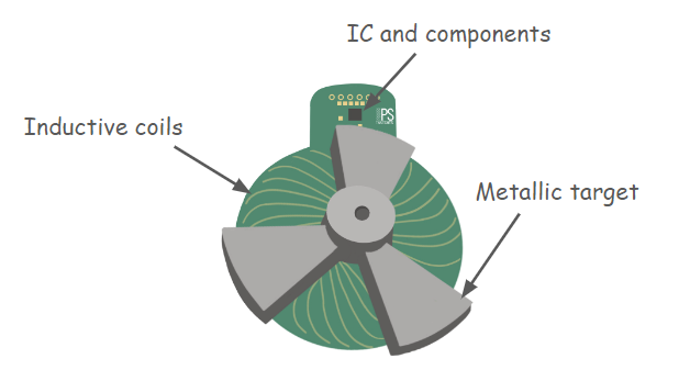
Figure 1. Inductive position sensor assembly. This example is an inductive rotary position sensor with a five-lobed target, giving a range of 360 deg / 3 = 120 deg. Within this range the sensor outputs an angle from 0 to 360 deg. We define 120 deg as one electrical period spanning 360 deg electrical: 1 deg = 3 deg electrical. In general, if N is the number of lobes on the target, 1 deg = N deg electrical. Other topologies, such as linear or arc sensors, are also possible.
Transmitter Coil (Tx Coil)
- The Tx coil is a multi-turn circular coil. Its diameter and number of turns determine its inductance.
- It achieves resonance through a pair of capacitors, tuned to a frequency between 2 and 5 MHz.
Receiver Coils (Rx Coils)
The Rx coil set consists of three independent coils designed to produce a three-phase signal that matches the target's periodicity. The design process involves several steps:
- Primitive function definition: define a primitive function that describes the basic path p(alpha) of the receiving coil, represented as r(theta) = B + A·sin(theta). Here A and B are constants determined by system dimensions, and theta is the angle ranging from 0 to 360 deg.
- Rx coil basic path definition: project the primitive function into polar coordinates, adapting it to the sensor periodicity: x = p(N·theta)×cos(theta) and y = p(N·theta)×sin(theta).
- Tx-Rx coupling removal: the Rx coil as defined above would exhibit non-zero coupling with the Tx coil. The objective is to achieve electromagnetic coupling only in the presence of the target. To accomplish this, we connect in series the path already obtained with a second path, an exact replica rotated by 180 deg electrical, generating an opposite coupling and therefore overall zero coupling with the transmission coil.
- Complete the design: replicate the Rx coil obtained above two more times, shifting them by 120 deg electrical and 240 deg electrical to obtain the full set of Rx coils. Add the Tx coil and the target.